555 Timer Schematic Symbol / Timer b in this method acts as a voltage comparator and has no timing function.. Timer b in this method acts as a voltage comparator and has no timing function. Its name is derived from three 5k ohm resistors,connected in series used in it.the timer ic can produce required waveform accurately. With this information you will learn how how the 555 works and will have the experience to build some of the circuits below. Only attach an 1k resistor + led from pin 3 to ground. Pin 2 is the trigger , which works like a starter's pistol to start the 555 timer running.
Only attach an 1k resistor + led from pin 3 to ground. Posted by on june 22, 2018. (1) for all available packages, see the orderable addendum at the end of the datasheet. Electronics tutorial about the 555 timer and how the 555 timer can be used as a 555 monostable the 555 timer ic is a very cheap, popular and useful precision timing device which can act as either if not, schematic wrong, or 555 defective. Transistor q3 is actually connected as a diode with the collector not carrying current.
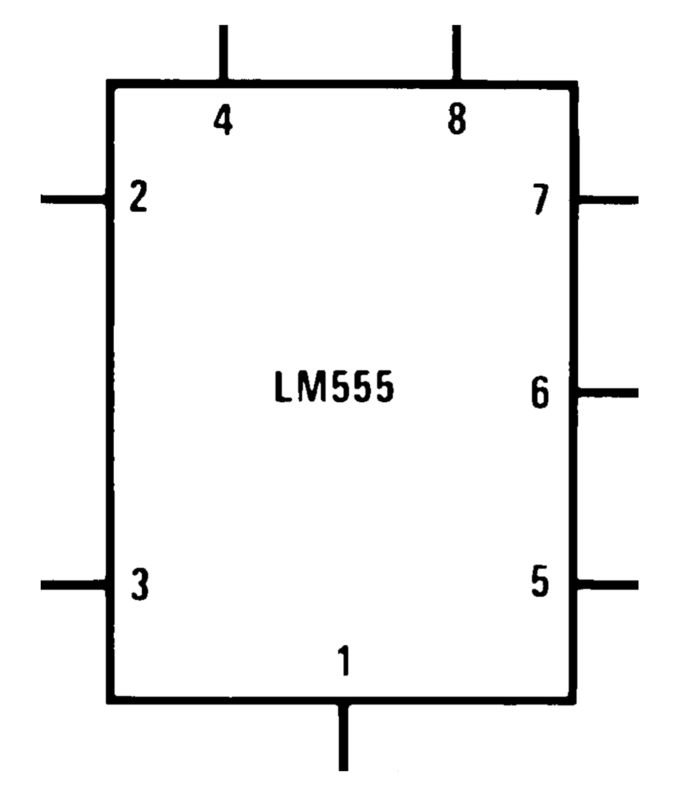
555 Timer IC PIN DIAGRAM - BragitOff.com from i0.wp.com And now a full schematic of the 555 timer oscillator with single step and free run option. Build a 555 timer ic tone generator out of snap circuits. Simple 555 timer circuits & projects. Although we could design our own ne555 timer using these building blocks in altium it is much easier to purchase the ic and create a schematic symbol for it instead. Schematic symbol of the 555 timer the 555 is an integrated circuit (chip) implementing a variety of timer and multivibrator applications. Pin 2 is the trigger , which works like a starter's pistol to start the 555 timer running. It's a simple source of oscillating current that can power blinking leds, generate tones, and lots of other useful applications. But when i complied, i got this.
The 555 timer chipis probably the most popular integrated circuit ever made.
Its name is derived from three 5k ohm resistors ,connected in series used in it.the timer ic can produce 555 timer was first introduced by signetics corporation in 1971 as se555/ne555. Only attach an 1k resistor + led from pin 3 to ground. The schematic shows (3) circuits, because one circuit does not work well over the entire vcc range. Tone generators have a number of uses in electronics. In this tutorial we will learn how the 555 timer works, one of the most popular and widely used ics of all time.
How to Build a 555 Timer Monostable Circuit from www.learningaboutelectronics.com Its function is to discharge the timing capacitor in astable and monostable circuits. Although a circuit common symbol is shown, the collector is not. The circuit layout is for a 555 timer in astable mode. This circuit generates a stable train of pulses. The 555 timer, designed by hans camenzind in 1971. So far i have tried drawing from this link which was supposed to produce. You can use the 555 chips for basic timing functions, such as turning a light on for a certain length of time, or you can use it to create a trigger: It is a affordable, stable and user friendly ic in.
555 timer is an industrial standard ic existing from early days of ic.
Introduced in 1971 by the american company signetics, the 555 is. How do i draw this schematic on latex? Because the electronic symbol is printed on each electronic component, once the project is completed, it will look almost exactly like an electronic schematic. Learn about the 555 timer and how it works in astable mode. It was designed in 1970 and introduced in 1971 by signetics (later acquired by philips). The basic 555 timer ic included in the chipkit™ starter kit is the ne555. With this information you will learn how how the 555 works and will have the experience to build some of the circuits below. Outputs an oscillating pulse signal. The 555 timer ic is an integrated circuit (chip) used in a variety of timer, delay, pulse generation, and oscillator applications. This circuit generates a stable train of pulses. Its name is derived from three 5k ohm resistors ,connected in series used in it.the timer ic can produce 555 timer was first introduced by signetics corporation in 1971 as se555/ne555. Tone generators have a number of uses in electronics. It does so thanks to feedback—the timing capacitor is connected to the trigger.
This circuit generates a stable train of pulses. Thank you, good subject about timer 555, timer 555 is encyclopedia in electronic engineering you can use it in more circuits and will be helpful, for arabic content about. The 555 timer is a simple integrated circuit that can be used to make many different electronic circuits. The 555 timer ic is an integrated circuit (chip) used in a variety of timer, delay, pulse generation, and oscillator applications. • in the time delay mode, the delay is controlled by • to understand how the capacitor is used in the 555 timer oscillator circuit, you must understand the basic charge and discharge cycles of the capacitor.
How to Read Electrical Schematics - Circuit Basics from www.circuitbasics.com Derivatives provide two (556) or four (558) timing circuits in one package. The 555 timer changes its output depending on the state of two inputs. Timer b in this method acts as a voltage comparator and has no timing function. In astable mode, the output cycles on and off continuously. The output of uc (upper comparator) which is reset input to rs latch is high when the threshold input is high or. Pin 2 is the trigger , which works like a starter's pistol to start the 555 timer running. The 555 timer is a simple integrated circuit that can be used to make many different electronic circuits. Monostable mode is great for creating time.
The 555 timer changes its output depending on the state of two inputs.
And now a full schematic of the 555 timer oscillator with single step and free run option. Basically, this means that you will have a continuous transition from a high voltage level (determined by and slightly less than your supply voltage) to 0v at a certain frequency (number of times per second). Pin 2 is the trigger , which works like a starter's pistol to start the 555 timer running. In the mwe, two tikz objects are created that can be placed and identified as the components in schematic editors such as proteus or eagle, pins will be identified. 5.29 shows a 555 timer configured as an astable or multistable multivibrator 66. It is a slave to timer a. Usually used to create time delays. Its function is to discharge the timing capacitor in astable and monostable circuits. Tone generators have a number of uses in electronics. It's a simple source of oscillating current that can power blinking leds, generate tones, and lots of other useful applications. There are several different part numbers that are 555 timers, and most of them are similar enough to ignore the differences, but check the data sheet for the particular limitations. Thank you, good subject about timer 555, timer 555 is encyclopedia in electronic engineering you can use it in more circuits and will be helpful, for arabic content about. Derivatives provide two (556) or four (558) timing circuits in one package.
Now the schematic symbol and pcb symbol are created for the 555 timer 555 timer schematic. The 555 timer ic is an integral part of electronics projects.


0 Komentar